Google News
logo
CISCO Nexus Interview Questions
The Cisco Nexus series switches are modular and fixed port network switches designed for the data center. Cisco Systems introduced the Nexus Series of switches on January 28, 2008. The first chassis in the Nexus 7000 family is a 10-slot chassis with two supervisor engine slots and eight I/O module slots at the front, as well as five crossbar switch fabric modules at the rear. Beside the Nexus 7000 there are also other models in the Nexus range.
 
Cisco NX-OS (Nexus Operating System) is a Modern data center-class networking operating system built with modularity, resiliency, and serviceability at its foundation. It is Robust operating system than Cisco-iOS. It supports distributed multithreaded processing on symmetric multiprocessors (SMPs), multi-core CPUs, and distributed data module processors. It was based on the industry-proven Cisco SAN-OS Software, Cisco NX-OS helps ensure continuous availability and sets the standard for mission-critical data center environments. NX-OS uses a kickstart image and a system image, except for Nexus 9000.
Although the Nexus 5000 had some modular capabilities and you can attach the Nexus 2000 fabric extender to the 5500 range, the Nexus 7000 is the real modular switch in the Nexus family with six versions: one 4 slot, one 9 slot, two 10 slot and two 18 slot switches.
The Cisco Nexus core switching system is taking the datacenter by storm, and there are good reasons why IT professionals are making it the heart of their server and storage systems. The transition to densely virtualized servers with rapid access to shared storage has coincided with the ready availability of 10G Ethernet ports on servers, and these 10G Ethernet ports all have to be connected together with a high speed switching fabric.  
 
The Nexus switches have three main advantages that improve the reliability, speed, and flexibility of this switched network :
* Fabric Extenders.
* Virtual Port Channel.
* Unified Fabric.
Network Admins like to have all the servers connect to one or two main switches, while Server Admins like to have their servers connect to switches at the top of the rack. With traditional Ethernet switches, there are disadvantages to both architectures. Traditional End of Row (or Middle of Row) switching design creates monstrous patch cable tangles, while traditional Top of Rack switching leads to reliability and bandwidth issues. The ideal would be to have one or two switches that can be centrally managed, yet have extensions at the top of each rack for easy server connection.
 
The Nexus switches have a unique design where remote Fabric Extenders act as remote shelves of the redundant core switches. Each Nexus 2000 Fabric Extender is controlled through multiple 10G copper or fiber uplinks by one Nexus 5000 or 7000 switch, with all management and switching decisions done by the parent switch. Each Fabric Extender can also have a secondary parent, creating reliability though redundancy. A typical deployment would have dual Nexus 2000 FE’s at the top of the rack for servers to dual-home connect to, and would have multiple uplinks to the Middle of Row or End of Row Nexus 5000 or 7000’s. This design creates a high speed and reliable core switching system with straightforward patch cable layouts.
Datacenters that have multiple rows of server and storage racks are best served by having multiple logical layers of switches, with the traditional design being Core, Distribution, and Access. Servers, storage, and virtualization systems work best when the systems are all in the same Layer 2 organization. The problem is that Layer 2 loop control mechanisms have issues. For example, the most consistently reliable protocol, Spanning Tree Protocol, prevents traffic from traversing half the uplinks by design. That means in a traditional switching environment, uplinks from access to distribution layer switches do not have enough bandwidth, slowing the information transfer where it is needed the most. When possible, Port Channels are used to provide multiple parallel uplinks, but this only works to a single distribution switch, and does not scale well to larger environments.
 
The Cisco Nexus architecture addresses this issue head on with the adoption of the Virtual Port Channel protocol. It is a special communication between redundant Distribution layer switches that allows for two switches to negotiate Port Channels with any type of Access layer switches. For example, if the Distribution layer was composed of two Nexus 5000 series switches, and the Access layer used existing Cisco Catalyst switches, you could set up Port Channels on each of the access switches, uplink them to both Nexus 5000 switches, and have all uplinks active all the time! Even better, with a setup of dual Nexus 7000 switches at the distribution layer, Nexus 5000’s and 2000’s at the access layers, all of the 10G links will be active with no loops or blocking.
Data centers have traditionally operated a dedicated storage network. This means each server required Ethernet Network Interface Cards and Fibre Channel Host Bus Adapters. With the adoption of 10G Ethernet on the servers, IT administrators are evaluating other options. This has to be done in conjunction with storage array manufacturers because the arrays have to connect into the network somehow. At this point in time, storage arrays are offered with connection at 8G Fibre Channel, 10G iSCSI, 10G Fibre Channel over Ethernet, 10G ATA over Ethernet, and 10G Network Attached Storage.
 
A dedicated Fibre Channel network has traditionally had an advantage for storage, because it was designed from the beginning to transport SCSI packets fast and reliably. Anything transporting storage over Ethernet has usually had slower performance because protocols had to be put into place to retransmit dropped packets. If the Ethernet network could provide high speed, lossless transmission of SCSI packets with low overhead, it could be a replacement for the Fibre Channel Storage Area Network.
 
The Nexus Unified Fabric provides upgrades to the Ethernet network to enable high speed lossless transport of Fibre Channel information packets with low overhead through the use of the Fibre Channel over Ethernet protocol. This allows for the gradual elimination of the older and slower SAN. But no organization is going to go out and replace all their existing storage arrays with new ones that have FCoE interfaces on them. So the Nexus 5000 has a special feature that enables conversion from Fibre Channel to FCoE.
 
The universal ports on the Nexus 5000 allows for any port to have Ethernet or Fibre Channel interfaces. Internally the Nexus Operating System (NX-OS) can map VSAN’s to VLAN’s, and will encapsulate the Fibre Channel traffic into Ethernet frames. To enable lossless transmission of storage at Layer 2 with low overhead, the Nexus switches are set up with Quality of Service to prioritize the storage traffic over all other traffic. This combination of features on the Nexus switches provided for a true datacenter Unified Fabric.
CISCO MDS 9000 SAN switches : These switches are used to support Data Center SAN infrastructure.
 
Nexus 1000V series switches : It is software-based switch. It operates inside the VMware ESX hypervisor and utilizes the NX-OS Software.
 
Nexus 2000 series switches : It is used to utilizes FEX technology to provide flexible data center deployment models and to meet the growing server demands.
 
Nexus 3000 series switches : these switches deliver Layer 2 and 3 switching for general-purpose deployments, high performance computing, (HPC) high-frequency trading (HFT), massively scalable data center (MSDC) and cloud networks.
 
Nexus 5000 series switches : These switches are high density Layer 2 & 3, 10/40G ethernet unified ports. It supports any number of ingress source ports and any number of sources VLANs or VSANs.
 
Nexus 7000 series switches : It can provide an end-to-end data center architecture on a single platform, including data center core, aggregation, and access layer. These series switch offer high-density 10G, 40G, and 100 Gigabit Ethernet and bandwidth per slot up to 1.3Tbps. It supports for FEX, virtual Port Channel (vPC), VDC, MPLS and Fabricpat. It was specifically developed for the most mission-critical enterprise and service provider deployments.
 
Nexus 9000 series switches : It can operate Nexus OS or Application Centric Infrastructure (ACI) modes. It offers both modular (9500 switches) and fixed (9300 switches) 1G,10G, 40G, and 100 Gigabit Ethernet (GE) configurations. It supports for Fabric Extender Technology (FEX), virtual Port Channel (vPC), and Virtual Extensible LAN (VXLAN).
Cisco DCNM stands for Data Centre Network Manager. It is a central management dashboard for data-center fabrics based on Cisco Nexus switches, MDS and Cisco UCS. The main purpose of DCNM is used to reduce the operation expanses by providing the efficient operations, monitoring and troubleshooting the Data Center network infrastructure. It provides a graphical user interface for viewing and managing switches, as well as a RESTful API to enable automation.
9000 Series switches offer fixed 9300 and 9200 series switches and modular 9500 series switches with 100/40/50/25/10/1 GE switch configurations. 9300 and 9500 switches are optimized for delivering enhanced operational flexibility while 9200 series switches are optimized for delivering high performance.
 
Cisco 9000 series switches are ideal either for traditional or for fully automated DC deployments. Below listed are the major capabilities/features of 9000 series switches, have a look –
 
Programmability : For provisioning L2 and L3 features, these switches provide an open-object API.Provides extensibility via Linux containers and Broadcom, Linux shell access and a Route Processor Module application package.Makes use of Cisco Nexus operating system API for web-based programmatic access.Simplifies the management of infrastructure by integrating with DevOps automation tools.

Architectural Flexibility : These switches can easily be deployed in energy-efficient leaf-spine or 3-tier architecture.It provides scalable as well as flexible virtual extensible multi-tenancy.Offers a foundation for Application Centric Infrastructure (ACI), delivering agility, flexibility and simplicity as well as for automating the application deployment.For the purpose of automating fabric configuration and management, these switches support Fabric Manager.

Real-Time Visibility and Telemetry : These switches offer Cisco Tetration Analytics support along with built-in hardware sensors for line-rate data collection and rich traffic flow telemetry.It also offers Cisco Data Broker support for analysis and network traffic monitoring.Real-time buffer utilization per port and per queue, for application traffic patterns and monitoring traffic micro-bursts.
Recommended read: Benefits, Features, and Everything about Cisco Nexus 6001 Series Switches
 
High Availability : Patching and ISSU (In-Service Software Upgrade) without any interruption with operations.These switches have components which are hot-swappable and fully redundant.Improves performance as well as reliability with the mix of ASICs and third-party performance.

Scalability : These switches offer up to 60 Tbps of nonblocking performance along with the latency of less than 5-microsecond.These switches also feature line rate, high density 100/50/40/25/10 Gbps L2 and L3 Ethernet ports.Offers bridging, wire-speed gateway, routing, and Border Gateway Protocol Control Plane.

Investment Protection : Allows the re-usage of existing 10 Gigabit Ethernet cabling plant for the 40 Gigabit Ethernet with 40-Gbps bi-directional transceiver.Supports Nexus 2000 Series FEX in both ACI modes and NX-OS.These switches facilitate migration from the NX-OS mode to ACI mode.
Like other Cisco Nexus switches, Cisco 9000 switches also have numerous different models. Here, we will give you a quick glimpse of all the models.
 
There are three models of Cisco 9000 switches :
 
* Cisco Nexus 9200 Switch Series
* Cisco Nexus 9300 Switch Series
* Cisco Nexus 9500 Switch Series
 
Cisco Nexus 9200 Switch Series : Cisco 9200 series has ultra-high-density and fixed-configuration DC switches with line rate L2 and L3 features. Cisco 9200 switches are specially designed for programmable fabric which provides mobility, flexibility and scale for IaaS (infrastructure-as-a-service), cloud providers and service providers.
 
In addition, these switches are also perfect for the programmable network which automates management and configuration for customers willing to take advantage of DevOps operation model as well as tool sets.                

Cisco Nexus 9200 Switch Series
Cisco Nexus 9300 Switch Series : Cisco 9300 series switches offer high-density 100/50/40/25/10 Gigabit Ethernet along with hybrid configurable ports for migration and flexible access deployment. This series of Cisco 9000 switches offer two platforms, which are –
 
* Cisco 9300-EX switches
* Cisco 9300-FX switches
 
These 9300 platforms are perfect for a modern system architecture which is designed for providing high-performance as well as for meeting the requirements of highly scalable DCs.
 
Cisco Nexus 9500 Switch Series : Cisco 9500 switches offer 100-Gbps connectivity and flexible ACI deployments as well as NX-OS mode. This series of Nexus 9000 has L2 and L3 non-blocking Ethernet switches having backplane bandwidth up to 172.8 Tbps (terabits per second).  Nexus 9500 switches are options available in 3 modular which are 
Cisco Nexus 9500 Switch Series
* Cisco 9504 Switch
* Cisco 9508 Switch
* Cisco 9516 Switch
A virtual PortChannel (vPC) allows links that are physically connected to two different Cisco Nexus™ 5000 Series devices to appear as a single PortChannel to a third device. The third device can be a Cisco Nexus 2000 Series Fabric Extender or a switch, server, or any other networking device. A vPC can provide Layer 2 multipathing, which allows you to create redundancy by increasing bandwidth, enabling multiple parallel paths between nodes and loadbalancing traffic where alternative paths exist.
 
After you enable the vPC function, you create a peer keepalive link, which sends heartbeat messages between the two vPC peer devices.
 
The vPC domain includes both vPC peer devices, the vPC peer keepalive link, the vPC peer link, and all the PortChannels in the vPC domain connected to the downstream device. You can have only one vPC domain ID on each device.
 
A vPC provides the following benefits:
 
* Allows a single device to use a PortChannel across two upstream devices
* Eliminates Spanning Tree Protocol blocked ports
* Provides a loop-free topology
* Uses all available uplink bandwidth
* Provides fast convergence if either the link or a device fails
* Provides link-level resiliency
* Helps ensure high availability
 
The vPC not only allows you to create a PortChannel from a switch or server that is dual-homed to a pair of Cisco Nexus 5000 Series Switches, but it can also be deployed along with Cisco Nexus 2000 Series Fabric Extenders.
* vPC : vPC refers to the combined PortChannel between the vPC peer devices and the downstream device.

* vPC peer switch : The vPC peer switch is one of a pair of switches that are connected to the special PortChannel known as the vPC peer link. One device will be selected as the primary device, and the other will be the secondary device.
 
* vPC peer link : The vPC peer link is the link used to synchronize states between the vPC peer devices. The vPC peer link carries control traffic between two vPC switches and also multicast, broadcast data traffic. In some link failure scenarios, it also carries unicast traffic. You should have at least two 10 Gigabit Ethernet interfaces for peer links.
 
* vPC domain : This domain includes both vPC peer devices, the vPC peer keepalive link, and all the PortChannels in the vPC connected to the downstream devices. It is also associated with the configuration mode that you must use to assign vPC global parameters.
 
* vPC peer keepalive link : The peer keepalive link monitors the vitality of a vPC peer switch. The peer keepalive link sends periodic keepalive messages between vPC peer devices. The vPC peer keepalive link can be a management interface or switched virtual interface (SVI). No data or synchronization traffic moves over the vPC peer keepalive link; the only traffic on this link is a message that indicates that the originating switch is operating and running vPC.
 
* vPC member port : vPC member ports are interfaces that belong to the vPCs. 
Fabric path is a Cisco proprietary switching protocol that in some ways replaces STP (Spanning Tree Protocols) and vPC (Cisco virtual port-channel). Fabric Path combines both Layer 2 and Layer 3 functions, thus giving simplicity of Layer 2 and also the intelligence of Layer 3.
FCoE stands for Fibre Channel over Ethernet. It is a technology that enables unified I/O on servers. Unified I/O is the ability to carry both storage and LAN data traffic on the same network adapter.
A Fibre Channel over Ethernet (FCoE) transit switch is a Layer 2 Data Center Bridging (DCB) switch that can transport FCoE frames. When used as an access switch for FCoE devices, the FCoE transit switch implements FCoE Initialization Protocol (FIP) snooping. A DCB switch transports both FCoE and Ethernet LAN traffic over the same network infrastructure while preserving the class of service (CoS) treatment that Fibre Channel (FC) traffic requires.
 
Benefits of an FCoE Transit Switch :
* Supports both storage network and traditional IP-based data communications, transporting both FCoE and Ethernet LAN traffic on the same switch without additional cost of powering, cooling, provisioning, maintaining, and managing your network.
 
* Provides the class of service that Fibre Channel traffic requires.
FCoE traffic should use a VLAN dedicated only to FCoE traffic. The Ethernet interfaces that connect to FCoE devices must include a native VLAN to transport FIP traffic, because devices exchange FIP VLAN discovery and notification frames as untagged packets. As a result, we recommend that you keep the native VLAN separate from the VLANs that carry the FCoE traffic. Other types of untagged traffic might use the native VLAN.
 
Keep the following in mind when setting up FCoE VLANs on FCoE transit switches :
 
* When a switch acts as a transit switch, the VLANs you configure for FCoE traffic can use any of the switch ports because the traffic in both directions is standard Ethernet traffic, not native FC traffic.
 
* On switches and QFabric system Node devices that do not use Enhanced Layer 2 software (ELS), you use only one CLI command to configure the native VLAN on the FCoE interfaces that belong to the FCoE VLAN :
 
set interfaces interface-name unit unit family ethernet-switching native-vlan-id native-vlan-id
On switches that use ELS software, you use two CLI commands to configure a native VLAN on FCoE interfaces:
 
* Configure the native VLAN on the interface : set interfaces interface-name native-vlan-id vlan-id
 
* Configure the port as a member of the native VLAN : set interfaces interface-name unit unit family ethernet-switching native-vlan-id vlan-id
 
* An FCoE VLAN (any VLAN that carries FCoE traffic) supports only Spanning Tree Protocol (STP) and link aggregation group (LAG) Layer 2 features.
 
* FCoE traffic cannot use a standard LAG because traffic might be hashed to different physical LAG links on different transmissions. This breaks the (virtual) point-to-point link that Fibre Channel traffic requires. If you configure a standard LAG interface for FCoE traffic, FCoE traffic might be rejected by the FC SAN.
 
* QFabric systems support a special LAG called an FCoE LAG, which you can use to transport FCoE traffic and regular Ethernet traffic (traffic that is not FCoE traffic) across the same link aggregation bundle. Standard LAGs use a hashing algorithm to determine which physical link in the LAG is used for a transmission, so communication between two devices might use different physical links in the LAG for different transmissions. An FCoE LAG ensures that FCoE traffic uses the same physical link in the LAG for requests and replies in order to preserve the virtual point-to-point link between the FCoE device converged network adapter (CNA) and the FC SAN switch across the QFabric system Node device. An FCoE LAG does not provide load balancing or link redundancy for FCoE traffic. However, regular Ethernet traffic uses the standard hashing algorithm and receives the usual LAG benefits of load balancing and link redundancy in an FCoE LAG.
Cisco NX-OS Release 5.0(3)N2(1) and later releases, FCoE NPV is supported on the Cisco Nexus 5000 Series devices. The FCoE NPV feature is an enhanced form of FCoE Initialization Protocol (FIP) snooping that provides a secure method to connect FCoE-capable hosts to an FCoE-capable FCoE forwarder (FCF) device. The FCoE NPV feature provides the following benefits :
 
* FCoE NPV does not have the management and troubleshooting issues that are inherent to managing hosts remotely at the FCF.
 
* FCoE NPV implements FIP snooping as an extension to the NPV function while retaining the traffic-engineering, vsan-management, administration, and trouble shooting aspects of NPV.
 
* FCoE NPV and NPV together allow communication through FC and FCoE ports at the same time, which provides a smooth transition when moving from FC to FCoE topologies.
MPLS stands for Multiprotocol label switching. It is a one of the techniques for routing network packets. It is protocol-agnostic and speeds up packet forwarding and routing. In a traditional, non-MPLS network, packets are routed at each hop. It is mainly focused on IPv6 and Ipv4. MPLS works only between OSI Layer-2 (Data link Layer) and Layer 3 (Network Layer) and it’s often known as a layer of 2.5 protocol.
Overlay Transport Virtualization(OTV) is s an IP-based mechanism developed by Cisco to provide Layer 2 extension capabilities over any sort of WAN-based transport infrastructure. It means a control plane protocol is used to exchange MAC reachability information between network devices providing LAN extension functionality.
Follow below code :
 
show running-config {vdc | vdc-all}
 
show vdc [vdc-name]
 
show vdc detail
 
show vdc current-vdc
 
show vdc membership [status]
 
show vdc resource template
 
show resource
 
show vdc [vdc-name] resource [resource-name]
 
show mac vdc {vdc-id}
Both VPC and VSS are used basically to support multi-chassis ether-channel that means we can create a port-channel whose one end is device A, however, another end is physically connected to 2 different physical switches which logically appears to be one switch.

SNo VPC VSS
1 Feature specific to Nexus Feature specific to catalyst 6500,4500 Series
2 Separate control plane for both switches. 2 Switches merge to form 1 logical Switch with a single control plane.
3 Separate IP for each switch management and configuration. Single IP for management and configuration of 1 Logical Unit (2 Physical Chassis)
4 HSRP is required. First Hop Redundancy Protocol like HSRP not required.
5 Separate instance of STP, FHRP, IGP, BGP etc. will be required on each physical Switch of VPC. Same instance of STP, FHRP, IGP, BGP etc. will be used on each physical Switch of VSS.
6 Both the switches are active and work individually. Only from VPC perspective are they elected primary and secondary. Switches are always primary and secondary from all aspects.
7 Supports L2 Port Channels Supports L3 Port Channels
8 Supports LACP Supports PAGP and LACP
9 Control messages are carried by CFS over Peer Link and a Peer keep alive link is used to check heartbeats and detect dual-active condition Control messages and Data frames flow between active and standby via VSL
MLAG vs vPC: 4 Key Differences
Both MLAG and vPC can create a port group between two switches and enable Layer 2 multipathing. In MLAG or vPC domain, each switch is managed and configured independently and is able to forward/route traffic without passing to a master switch. Despite their similarities, they still differ in some ways.
 
Difficulty of implementation : Obviously, the biggest difference between them is the difficulty of implementation. MLAG is a public protocol that is supported by almost every vendor using their own custom rolled implementation, while vPC is a Cisco Nexus specific protocol, not all the vendors have this technology. Thus, MLAG setup is a bit easier than vPC.
 
Compatibility issues : Another issue is compatibility. For vPC pairing, the same type of Cisco Nexus switches must be used. For example, it is not possible to configure vPC on a pair of switches including a Nexus 7000 series and a Nexus 5000 series switch. And the vPC peers must run the same NX-OS version except during the non-disruptive upgrade, that is, In-Service Software Upgrade (ISSU).
 
Layer multipathing : Besides, the vPC peer link must consist of at least two 10G Ethernet ports in dedicated mode. vPC is more advanced than MLAG. It supports both Layer 2 and Layer 3 multipathing, which allows you to create redundancy by enabling multiple parallel paths between nodes and load-balancing traffic where alternative paths exist. And if you want to enable Layer 3 multipathing, you could also use the Multi-Active Gateway Protocol (MAGP).
 
Application scenarios : Normally, vPC can only be used on Cisco Nexus data center switches, while MLAG can be applied to a wide range of scenarios. Whether in a traditional 3-tier data center architecture or a 2-tier spine-leaf architecture, switches that support MLAG can form an MLAG pair at different layers. All FS data center switches support MLAG. By using MLAG in data center network design, FS data center switches help deliver system level redundancy and improve network reliability.

Item MLAG vPC
Simplifies Network Design Yes Yes
Eliminates Spanning Tree Protocol (STP) Yes Yes
Multipathing Layer 2 Layer 2 & Layer 3
Difficulty of Implementation Easier Relatively Difficult
Switch Type for Pairing No requirement Strict Requirements
Using Scenarios Common seen in distribution or data center switches Usually in Cisco Nexus data center switches
FabricPath is supported on all F1 and F2 modules. FCoE is supported on all F1 modules and F2 modules except on the 48 x 10GE F2 (Copper) module. FEX is supported on all F2 modules. Use this link from Cisco as a reference.
 
F2e module supports FCoE, FEX, and FabricPath. The F3 module (12 port 40GE) supports FEX, FabricPath, FCoE, OTV, MPLS and LISP.
Catalyst switches offer advanced customization and manageability. The switches can be configured using a serial console, telnet or Secure Shell. Simple Network Management Protocol (SNMP) allows monitoring of many states, and measurement of traffic flows. Many devices can also run an HTTP server.
 
Configuration of the switch is done in plain text and is thus easy to audit. No special tools are required to generate a useful configuration. For sites with more than a few devices, it is useful to set up a Trivial File Transfer Protocol (TFTP) server for storing the configuration files and any IOS images for updating. Complex configurations are best created using a text editor (using a site standard template), putting the file on the TFTP server and copying it to the Cisco device. However, it can be noted that a TFTP server can present its own security problems.
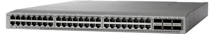
There are two general types of Catalyst switches : fixed configuration models that are usually one or two rack units in size, with 12 to 80 ports; and modular switches in which virtually every component, from the CPU card to power supplies to switch cards, are individually installed in a chassis.
 
In general, switch model designations start with WS-C or C, followed by the model line (e.g. C9600). A letter at the end of this number signifies a special feature, followed by the number of ports (usually 24 or 48) and additional nomenclature indicating other features like UPOE (e.g. C9300-48U). Catalyst 9000 switches also include software subscription license indicators (e.g. C9200-48T-P, E for Essentials, A for Advantage and P for Premier)
 
Fixed-configuration switches :
* Cisco Catalyst 9500 Series : Layer 2 and layer 3 stackable core switches.
* Cisco Catalyst 9300 SeriesLayer 2 and layer 3 stackable access and distribution switches.
* Cisco Catalyst 9200 Series : Layer 2 and layer 3 stackable access switches.
* Cisco Catalyst 3850 seriesLayer 2 and layer 3 stackable access and distribution switches.
* Cisco Catalyst 3650 seriesLayer 2 and layer 3 switches with optional stacking capability.
* Cisco Catalyst 2960-X/XR SeriesLayer 2 and layer 3 stackable access switches.
* Cisco Catalyst 2960-L Series : Layer 2 and layer 3 access switches.
* Cisco Catalyst 3560CX/2960CX SeriesCompact, fanless layer 2 and layer 3 switches.
* Cisco Catalyst Digital Building Series : Compact, fanless layer 2 and layer 3 switches.

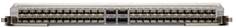
Modular switches : Cisco modular switches offer a configurable selection of chassis, power supplies, line cards and supervisor modules. Among Cisco's modular series are:
 
* The Cisco Catalyst 9600 Series is a modular chassis-based core switch family. This series can support interfaces up to 100 Gigabit Ethernet in speed and redundant sSupervisor modules, power supplies and fans.

* The Cisco Catalyst 9400 Series is a chassis-based access and distribution switch family. This series can support interfaces up to 40 Gigabit Ethernet in speed and redundant supervisor modules, power supplies and fans.

* The Cisco Catalyst 6800 Series is a chassis-based switch family. This series can support interfaces up to 40 Gigabit Ethernet in speed and redundant supervisor modules.

* The Cisco Catalyst 6500 Series is a chassis-based switch family. This series can support interfaces up to 40 Gigabit Ethernet in speed and redundant supervisor modules.

* The Cisco Catalyst 4500 Series is a mid-range modular chassis network switch. The system comprises a chassis, power supplies, one or two supervisors, line cards and service modules. The Series includes the E-Series chassis and the Classic chassis which is manufactured in four sizes: ten-, seven-, six-, and three-slot.
The Nexus 2000 Fabric Extender does not perform any local switching functions, and all traffic is forwarded to the parent switch such as Nexus 5K,7K,9K.
 
The Nexus 2200 Fabric Extenders can be connected to the parent switches using two different methods,
 
a) Static interface pinning
b) Dynamic interface pinning
 
Static interface pinning : 
* In Static Interface Pinning method, A group of ports in Fabric Extender and assign this ports manually with one uplink for sending traffic to the parent switch.
 
* If one particular uplink fails, a group of FEX ports associated with this uplink, fail as well.
 
* The pinning is based on the number of uplinks available to the Parent Switch.
 
* Static pinning is recommended when you want tight control over the bandwidth and oversubscription in the network.
 
Dynamic interface pinning
* In Dynamic Interface Pinning method, we use port channel to connect from Fabric Extender to Parent Switch instead of connecting the interfaces directly.
 
* If one of the particular uplink fails, a group of FEX ports associated with this uplink does not fail as we are using port channel to connect parent switch.
 
* The choice of pinning mode depends upon the way how the servers are connected to the access switches.
 
* For dual-homed servers, static pinning results in more deterministic oversubscription ratios. However, for single-homed servers, dynamic pinning provides increased availability.
Nexus Pinning
Configuration of Pinning : 
 
N5K(config-fex)# description FEX100
N5K(config-fex)# exit
N5K(config)# interface ethernet 1/1
N5K(config-if)# switchport mode fex-fabric
N5K(config-if)# fex associate 100
N5K(config-if)# no shutdown
N5K(config)# interface ethernet 1/2
N5K(config-if)# switchport mode fex-fabric
N5K(config-if)# fex associate 100
N5K(config-if)# no shutdown
NEXUS members can use the automated kiosks located in the U.S. Preclearance area and the Canadian inspection services area at participating airports.
 
Members can proceed directly to the NEXUS self-serve kiosk and do not need to go through the standard queue to speak to a border services officer or CBP officer.
 
Members stand in front of the self-serve kiosk and look into the adjustable camera and follow the audio instructions so that their irises can be photographed using iris recognition biometric technology.
 
Once the CBSA or CBP has confirmed that the photo of the irises matches the one on file, the member will use the touch screen to answer standard customs and immigration questions.
 
NEXUS members residing in Canada can use a Traveller Declaration Card (TDC) to declare goods and pay for any duties or taxes when entering Canada. Members simply deposit a TDC in a secure TDC box conveniently located near a self-serve kiosk. Any duties or taxes owing will be collected through the credit card information provided on the TDC.
Orphan ports are single attached devices that are not connected via a vPC, but still carry vPC VLANs. In the instance of a peer-link shut or restoration, an orphan port’s connectivity may be bound to the vPC failure or restoration process. Issue the show vpc orphan-ports command in order to identify the impacted VLANs.
29 .
Is Nexus 7010vpc Feature (lacp Enabled) Compatible With The Cisco Asa Etherchannel Feature And With Ace 4710 Etherchannel?
With respect to vPC, any device that runs the LACP (which is a standard), is compatible with the Nexus 7000, including ASA/ACE.
30 .
Which Nexus 7000 Modules Support Fibre Channel Over Ethernet (fcoe)?
The Cisco Nexus 7000 Series 32-Port 1 and 10 Gigabit Ethernet Module support FCoE. The part number of the product is N7K-F132XP-15.
On a Nexus, use a route-map command with a set clause of metric-type type-[½] in order to have the same functionality as in IOS using the default-information originate always metric-type [½] command.
 
For example :
* switch(config)#route-map STAT-OSPF, permit, sequence 10
* switch(config-route-map)#match interface ethernet 1/2
* switch(config-route-map)#set metric-type {external | internal | type-1 | type-2}
This error message is generated because the port is not FEX capable:
 
N7K-2(config)#interface ethernet 9/5
N7K-2(config-if)#switchport mode fex-fabric

ERROR : Ethernet9/5: Configuration does not match the port capability
In the network backbone, or even core layer, a totally different method would be used to shorten STP convergence. It operates by having a switch actively determine whether or not alternative paths are available to the root bridge, in the event the switch detects an indirect link failure. Indirect link failures happen when a link which is not directly connected to a switch fails. A switch detects an indirect link failure any time it receives inferior BPDUs from its designated bridge on both its very own root port or a blocked port.
34 .
How to configure the BackboneFast in Switch use the command?
Use the below command :
 
Switch(config)# spanning-tree backbonefast.
35 .
There are multiple logical roles (Core & Distribution on the same box)
 
* VDCs as a managed service to customers
* lab environment for later production use
* some features cannot co-exist in the same VDC (OTV and SVIs)
Configure the vPC Keepalive Link and Messages
 
This example demonstrates a way to assemble the destination, supply informatics address, and VRF for the vPC-peer-keepalive link:
 
switch# assemble terminal
 
switch(config)# feature vpc
 
switch(config)# vpc domain a hundred
 
switch(config-vpc-domain)# peer-keepalive destination 172.168.1.2 source
 
172.168.1.1 vrf vpc-keepalive
 
Create the vPC Peer Link
On a Nexus, use a route-map command with a collection clause of metric-type type-[½] so as to possess an equivalent practicality as in IOS exploitation the default-information originate forever metric-type [½] command.
 
For example :
 
switch(config)#route-map STAT-OSPF, permit, sequence ten
 
switch(config-route-map)#match interface local area network 1/2
 
switch(config-route-map)#set metric-type internal
All interface link status (up/down) messages are logged by default. Link status events can be configured globally or per interface. The interface command enables link status logging messages for a specific interface.
 
For example :
* N7k(config)#interface ethernet x/x
* N7k(config-if)#logging event port link-status
The Nexus 7000 does not support a DHCP server, but it does support DHCP relay. For relay, use the ip dhcp relay address x.x.x.x interface command.

See Cisco Nexus 7000 Series NX-OS Security Configuration Guide, Release 5.x for more information on Dynamic Host Configuration Protocol (DHCP) on a Cisco NX-OS device.
The Scalable Feature License is the new Nexus 7000 system license that enables the incremental table sizes supported on the M-Series L Modules. Without the license, the system will run in standard mode, meaning none of the larger table sizes will be accessible. Having non-XL and XL modules in a system is supported, but for the system to run in XL mode all modules need to be XL capable, and the Scalable Feature license needs to be installed. Mixing modules is supported, with the system running in the non-XL mode. If the modules are in the same system, the entire system falls back to the common smallest value. If the XL and non-XL are isolated using VDCs, then each VDC is considered a separate system and can be run in different modes.
 
In order to confirm whether the Nexus 7000 has the XL option enabled, you first need to check if the Scalable Feature License is installed. Also, having non-XL and XL modules in a system is supported, but in order for the system to run in XL mode, all modules need to be XL capable.

Sources : Cisco, and more..