Google News
logo
CCNP Security Interview Questions
CCNP(Cisco Certified Network Professional) Security,  Manages security in Routers, Switches, Networking Devices, and appliances. The certified professional is responsible for configuring, supporting, and resolving Firewalls, VPNs, and IDS/IPS solutions for their networking environment They should be able to secure network design and execute with the help of Cisco Secure Access, Edge Network Security, Threat Control, and Secure Mobility solutions.
 
These professionals have an in-depth understanding of deploying Cisco’s Identity Services Engine and 802.1X secure network access. The CCNP Security experts deploy and monitor network access security by using the Cisco ISE appliance product solution. They set up different advance Cisco security solutions for mitigating outside threats and securing devices connecting to the network. The security personnel decreases the risk to IT infrastructures and applications using Cisco’s ISE appliance feature.
 
The CCNP Security professional offers operational support identity and network access control. They will identify and troubleshoot the Cisco network security appliances and the Cisco IOS Software devices that comprise your network's security. 
The difference between a CCNA and a CCNP can be stated as the CCNA certification is the associate-level certification that tests professionals on switching and routing fundamentals. It covers both wireless network access and wired network access along with routing principles before it covers FHRPs, IPv4/IPv6 static routing, and OSPFv2. It covers various IP services, including DHCP, NAT, and QoS. It also introduces network security by covering topics such as AAA, ACLs, VPNs, and secure wireless network access.
 
Whereas the CCNP is a more advanced certification that requires a deeper level of knowledge to install, troubleshoot, and maintain both LAN and WAN for systems of up to 100 to 500 nodes.  CCNP Enterprise has five exams that cover wireless design, SD-WAN, network design, automation, wireless implementation, and advanced routing in enterprise networks.

Criteria

CCNA

CCNP

Prerequisites There are no prerequisites for taking CCNA. While for CCNP, qualifying CCNA or CCIE in any track is a must.
Knowledge required It requires a test on routing fundamentals and switching. While CCNP requires a deep understanding and knowledge of LANs and WANs.
Skill Set CCNA Builds up a strong networking base. While CCNP exposes to the deep knowledge of advanced networking technologies.
Job roles Network technician, Service desk technician/Engineer, Helpdesk Engineer, Network support engineer, etc. IT Team Leader, System Engineer, Network Engineer, Network Specialist, Network Analyst, etc.
CCNP Security or CCNP R&S, both are equally good. It depends on your interest that what you like more. CCNP Security labs require more devices and It's less challenging to practice CCNP Routing and Switching in a virtual environment compared to CCNP Security. Almost every Cisco technician or engineer starts with CCNA Routing and Switching.
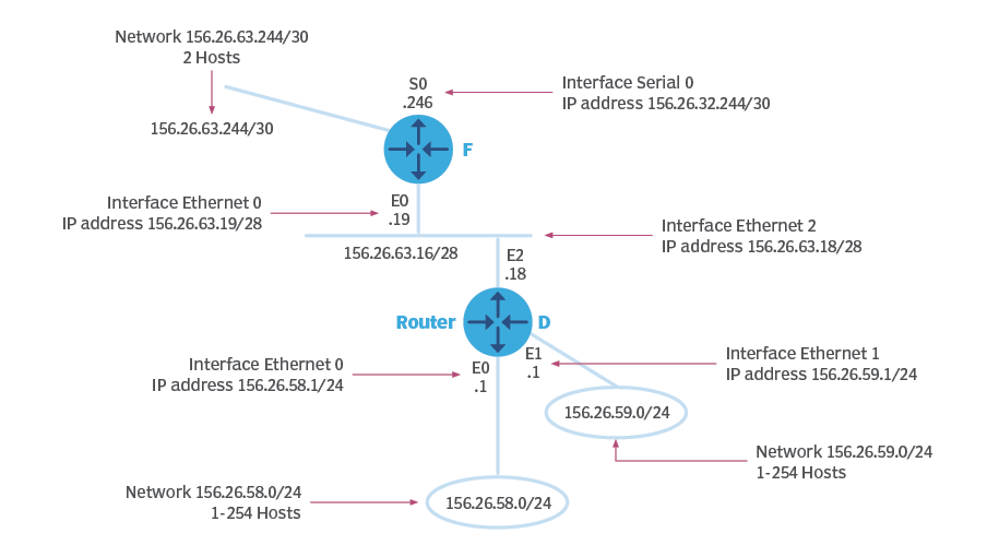
In large internetworks, hundreds, or even thousands, of network addresses can exist. It is often problematic for routers to maintain this volume of routes in their routing tables. Route summarization (also called route aggregation or supernetting) can reduce the number of routes that a router must maintain, because it is a method of representing a series of network numbers in a single summary address.
If a router needs to advertise 50 routes, it will need 50 specific lines in its update packet. As these routes increase, the number of lines required also increases, expanding packet size and the amount of bandwidth used. That means there will be less bandwidth available for actual data transfer.
 
Route summarization enables multiple routes to be advertised with only one line in an update packet, reducing the packet size and leaving more bandwidth for data transfer.
 
Also, each time a new data flow enters a router, it must identify which interface the traffic must be sent out to. For this, it must perform a lookup in its routing table. This process takes longer for large routing tables and requires more router central processing unit (CPU) cycles to route traffic.
 
Route summarization can eliminate this problem by minimizing both the time required to perform lookup and reducing the number of CPU cycles.

Network Teminology
Route aggregation offers several advantages, including the following:
 
* reduces the number of entries in the route table, which reduces the load on the router and network overhead for routing protocols;
* minimizes latency in a complex network, especially when many routers are involved;
* reduces or eliminates unnecessary routing updates after part of the network undergoes a change in CPU cycles topology;
* hides instability in the system behind the summary that remains valid even in the absence of summarized networks;
* saves memory since routing tables will be smaller in size;
* helps save bandwidth as there are fewer routes to advertise; and
* reduces processor workloads and saves, since there are fewer packets to process and smaller routing tables to work on.
There are two main disadvantages of route aggregation :
 
* Suboptimal routing. Misconfigured route summarization may result in suboptimal routing. Route summarization may also create inconsistent routing if a network has noncontiguous subnetworks. When using summaries, the router may prefer another path where it has learned a more specific network form, which may not be the most optimal routing method.

* Forwarding traffic for unused networks. If the router doesn't find a matching destination in its routing table, it will start dropping traffic, leading to data loss. Also, the summary route may cover unused networks. The router that has a summary route will forward traffic to the router that advertised the summary route.

To avoid suboptimal or incorrect routing and to prevent routers from inaccurately advertising networks or duplicating other routers' advertisements, it's important to design networks with summarization in mind. Advance planning and leaving room for future network growth can help with the design of a scalable network that supports route summarization.
Cisco Identity Services Engine (ISE) is a next-generation identity and access control policy platform that enables enterprises to enforce compliance, enhance infrastructure security, and streamline their service operations. The unique architecture of Cisco ISE allows enterprises to gather real-time contextual information from networks, users, and devices. The administrator can then use that information to make proactive governance decisions by tying identity to various network elements including access switches, wireless LAN controllers (WLCs), virtual private network (VPN) gateways, and data center switches.
 
Cisco ISE is a key component of the Cisco Security Group Access Solution.
 
Cisco ISE is a consolidated policy-based access control system that incorporates a superset of features available in existing Cisco policy platforms. Cisco ISE performs the following functions :
 
* Combines authentication, authorization, accounting (AAA), posture, and profiler into one appliance
* Provides for comprehensive guest access management for the Cisco ISE administrator, sanctioned sponsor administrators, or both
* Enforces endpoint compliance by providing comprehensive client provisioning measures and assessing device posture for all endpoints that access the network, including 802.1X environments
* Provides support for discovery, profiling, policy-based placement, and monitoring of endpoint devices on the network
* Enables consistent policy in centralized and distributed deployments that allows services to be delivered where they are needed
* Employs advanced enforcement capabilities including security group access (SGA) through the use of security group tags (SGTs) and security group access control lists (SGACLs)
* Supports scalability to support a number of deployment scenarios from small office to large enterprise environments
Below is an outline of the process that utilizes the migration utility provided by Cisco to migrate to the existing ACS configuration. These steps listed should be followed during a migration to make it successful. 
 
* Build the test ISE environment to validate the existing TACACS policies from ACS Server(s) 
* Utilize the ACS to ISE migration tool to migrate policies from production ACS to the test ISE server.  
 
Note : Policies can NOT be migrated from ACS to an existing instance of ISE via Cisco’s migration tool. Hence, a new test instance must be deployed to test and validate the migrated policies prior to production implementation. 
 
* Validate ISE policies in a test environment. 
* Migrate from production ACS to production ISE using either Parallel or In-Place migration as described below.  
 
ACS to ISE Parallel migration: 

How does it work? 
 
* Have existing ACS servers and ISE servers active at the same time  
* If an existing ISE deployment will be used for device administration, merge the configuration from test ISE server to the production ISE instance 
* Gradually migrate Network Device Administration capabilities, in a controlled manner, to prevent any disruption to IT operations 
* Full migration can be scheduled over several weeks 
* The “change window” for initial migration (for a limited number of devices) requires minimal downtime of, literally, a few minutes per device. 
 
Note : New IP Addresses for each ISE Server must be allocated when choosing the Parallel migration approach. The configuration of each network device must be modified to point TACACS requests to the new ISE Server(s)
BGP is consists of two flavors, these two flavors are as follows:
 
External BGP : used between autonomous systems
Internal BGP : used within the autonomous system.
 
External BGP is to exchange routing information between the different autonomous systems. In this lesson I explain why we need internal BGP. I would recommend to read it after finishing this lesson and learning about external BGP first.
11 .
NAT stands for network address translation. It’s a way to map multiple local private addresses to a public one before transferring the information. Organizations that want multiple devices to employ a single IP address use NAT, as do most home routers.
Let’s say that there is a laptop connected to a home router. Someone uses the laptop to search for directions to their favorite restaurant. The laptop sends this request in a packet to the router, which passes it along to the web. But first, the router changes the outgoing IP address from a private local address to a public address.
 
If the packet keeps a private address, the receiving server won’t know where to send the information back to — this is akin to sending physical mail and requesting return service but providing a return address of anonymous. By using NAT, the information will make it back to the laptop using the router’s public address, not the laptop’s private one.
 
NAT Types
There are three different types of NATs. People use them for different reasons, but they all still work as a NAT.
 
1. Static NAT : When the local address is converted to a public one, this NAT chooses the same one. This means there will be a consistent public IP address associated with that router or NAT device.
 
2. Dynamic NAT : Instead of choosing the same IP address every time, this NAT goes through a pool of public IP addresses. This results in the router or NAT device getting a different address each time the router translates the local address to a public address.
 
3. PAT : PAT stands for port address translation. It’s a type of dynamic NAT, but it bands several local IP addresses to a singular public one. Organizations that want all their employees’ activity to use a singular IP address use a PAT, often under the supervision of a network administrator.
If a delivery system is not divided into access, distribution, and core layers, every point in the system needs to maintain every possible destination address to make a delivery decision. The use of a layered system means each layer needs only the information necessary to deliver to the next layer.
The last four digits are used at the access layer to identify a particular telephone. The next three numbers are used at the distribution layer to identify an exchange that services several phone numbers. The area code is used at the core level for routing between different regions.
 
This is a speed drill. Using only your head, convert the following binary numbers to decimals.
 
11100000
11111100
10000000
11110000
00111111
 
224, 252, 128, 240, and 63 (64 – 1)
By default, the router stores all passwords in clear text and presents them in a human-readable format when you look at the router’s configuration. The service password-encryption command encrypts the passwords by using the Vigenere encryption algorithm.
 
Problem : You want to encrypt passwords so that they do not appear in plain text in the router configuration file.
 
Solution : To enable password encryption on a router, use the service password-encryption configuration command:
Router1#configure terminal 
Enter configuration commands, one per line.  End with CNTL/Z.
Router1(config)#enable password oreilly
Router1(config)#line vty 0 4
Router1(config-line)#password cookbook
Router1(config-line)#line con 0
Router1(config-line)#password cookbook
Router1(config-line)#line aux 0
Router1(config-line)#password cookbook
Router1(config-line)#exit
Router1(config)#service password-encryption
Router1(config)#end
Router1#
The first method of encryption that Cisco provides is through the command service password-encryption. This command obscures all clear-text passwords in the configuration using a Vigenere cipher. You enable this feature from global configuration mode.
Router#config terminal
Enter configuration commands, one per line.  End with CNTL/Z.
Router(config)#service password-encryption
Router(config)#^Z
Now a show run command no longer displays the password in humanly readable format.
enable secret 5 $1$Guks$Ct2/uAcSKHkcxNKyavE1i1
enable password 7 02030A5A46160E325F59060B01
!
username jdoe password 7 09464A061C480713181F13253920
username rsmith password 7 095E5D0410111F5F1B0D17393C2B3A37
!
line con 0
 exec-timeout 5 0
 password 7 110A160B041D0709493A2A373B243A3017
 login local
 transport input none
line aux 0
 exec-timeout 5 0
 password 7 0005061E494B0A151C36435C0D
 login tacacs
 transport input all
line vty 0 4
 exec-timeout 5 0
 password 7 095A5A1054151601181B0B382F
 login
 transport input ssh
The only password not affected by the service password-encryption command is the enable secret password. It always uses the MD5 encryption scheme.
 
While the service password-encryption command is beneficial and should be enabled on all routers, remember that the command uses an easily reversible cipher. Some commercial programs and freely available Perl scripts instantly decode any passwords encrypted with this cipher. This means that the service password-encryption command protects only against casual viewers—someone looking over your shoulder—and not against someone who obtains a copy of the configuration file and runs a decoder against the encrypted passwords. Finally, service password-encryption does not protect all secret values such as SNMP community strings and RADIUS or TACACS keys.
FA 16 = 250  10, CE16 = 20610, 1216 = 18 10, and 34 16 = 52 10
 
FACE1234 16 = 250.206.18.52 dotted decimal
Configure and debug Secure Shell (SSH) on Cisco routers or switches that run Cisco IOS® Software.
 
Prerequisites
Requirements
* The Cisco IOS image used must be a k9(crypto) image in order to support SSH. For example c3750e-universalk9-tar.122-35.SE5.tar is a k9 (crypto) image.
 
Components Used
The information in this document was created from the devices in a specific lab environment. All of the devices used in this document started with a cleared (default) configuration. If your network is live, ensure that you understand the potential impact of any command.
 
The information in this document is based on Cisco IOS 3600 Software (C3640-IK9S-M), Release 12.2(2)T1.
 
SSH was introduced into these Cisco IOS platforms and images:
 
* SSH terminal-line access (also known as reverse-Telnet) was introduced in Cisco IOS platforms and images start in Cisco IOS Software Release 12.2.2.T.
* SSH Version 2.0 (SSH v2) support was introduced in Cisco IOS platforms and images start in Cisco IOS Software Release 12.1(19)E.

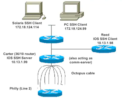
SSH v2 Network Diagram
A DMZ Network is a perimeter network that protects and adds an extra layer of security to an organization’s internal local-area network from untrusted traffic. A common DMZ is a subnetwork that sits between the public internet and private networks.
 
The end goal of a DMZ is to allow an organization to access untrusted networks, such as the internet, while ensuring its private network or LAN remains secure. Organizations typically store external-facing services and resources, as well as servers for the Domain Name System (DNS), File Transfer Protocol (FTP), mail, proxy, Voice over Internet Protocol (VoIP), and web servers, in the DMZ. 
 
These servers and resources are isolated and given limited access to the LAN to ensure they can be accessed via the internet but the internal LAN cannot. As a result, a DMZ approach makes it more difficult for a hacker to gain direct access to an organization’s data and internal servers via the internet.
Businesses with a public website that customers use must make their web server accessible from the internet. Doing so means putting their entire internal network at high risk. To prevent this, an organization could pay a hosting firm to host the website or their public servers on a firewall, but this would affect performance. So instead, the public servers are hosted on a network that is separate and isolated.
 
A DMZ network provides a buffer between the internet and an organization’s private network. The DMZ is isolated by a security gateway, such as a firewall, that filters traffic between the DMZ and a LAN. The default DMZ server is protected by another security gateway that filters traffic coming in from external networks.
 
It is ideally located between two firewalls, and the DMZ firewall setup ensures incoming network packets are observed by a firewall—or other security tools—before they make it through to the servers hosted in the DMZ. This means that even if a sophisticated attacker is able to get past the first firewall, they must also access the hardened services in the DMZ before they can do damage to a business.
 
If an attacker is able to penetrate the external firewall and compromise a system in the DMZ, they then also have to get past an internal firewall before gaining access to sensitive corporate data. A highly skilled bad actor may well be able to breach a secure DMZ, but the resources within it should sound alarms that provide plenty of warning that a breach is in progress.
 
Organizations that need to comply with regulations, such as the Health Insurance Portability and Accountability Act (HIPAA), will sometimes install a proxy server in the DMZ. This enables them to simplify the monitoring and recording of user activity, centralize web content filtering, and ensure employees use the system to gain access to the internet.
The main benefit of a DMZ is to provide an internal network with an advanced security layer by restricting access to sensitive data and servers. A DMZ enables website visitors to obtain certain services while providing a buffer between them and the organization’s private network. As a result, the DMZ also offers additional security benefits, such as:

Enabling access control : Businesses can provide users with access to services outside the perimeters of their network through the public internet. The DMZ enables access to these services while implementing network segmentation to make it more difficult for an unauthorized user to reach the private network. A DMZ may also include a proxy server, which centralizes internal traffic flow and simplifies the monitoring and recording of that traffic.

Preventing network reconnaissance : By providing a buffer between the internet and a private network, a DMZ prevents attackers from performing the reconnaissance work they carry out the search for potential targets. Servers within the DMZ are exposed publicly but are offered another layer of security by a firewall that prevents an attacker from seeing inside the internal network. Even if a DMZ system gets compromised, the internal firewall separates the private network from the DMZ to keep it secure and make external reconnaissance difficult.

Blocking Internet Protocol (IP) spoofing : Attackers attempt to find ways to gain access to systems by spoofing an IP address and impersonating an approved device signed in to a network. A DMZ can discover and stall such spoofing attempts as another service verifies the legitimacy of the IP address. The DMZ also provides network segmentation to create a space for traffic to be organized and public services to be accessed away from the internal private network.

Services of a DMZ include :
 
* DNS servers
* FTP servers
* Mail servers
* Proxy servers
* Web servers
Convert each octal digit into three binary digits, and then convert the binary result to hexadecimal. 001 010 011 100 101 110 111 000
0010 1001 1100 1011 1011 1000
 
29CBB8
198.4.81.0/27 and the subnets are: 198.4.81.0/27
 
198.4.81.32/27
198.4.81.64/27
198.4.81.96/27
198.4.81.128/27
198.4.81.160/27
198.4.81.192/27
198.4.81.224/27
Classless routing protocols advertise subnet mask information along with the network prefixes. Classful routing protocols do not. Therefore, for a classful protocol,  all subnets for the major network number being used must be the same length. Also, the classful protocol cannot support discontiguous network prefixes.
The passive state means that a router has a successor for a route. The active state means that a router does not have a successor or feasible successor for a route and is actively sending queries to neighbors to get information about the route.
The reported distance to a route that is sent to another router is the feasible distance on the reporting router. Feasible distance is the reported distance plus the metric between the receiving and reporting routers. The route with the lowest feasible distance is the successor. Any routes with a reported distance that is less than the feasible distance are feasible successors.
* 10.1.32.0/19
* 10.1.64.0/19
* 10.1.96.0/19

You need to examine the third byte because that is the byte where the four prefixes differ: 0 = 0 0 0 0 0 0 0 0
 
* 32 = 0 0 1 0 0 0 0 0
* 64 = 0 1 0 0 0 0 0 0
* 96 = 0 1 1 0 0 0 0 0

The last 7 bits are irrelevant, so the mask is 1 0 0 0 0 0 0 0 and the EIGRP command is ip summary-address eigrp 1 10.1.0.0 255.255.128.0.
Cisco® Security Manager is an enterprise-class security management application that provides insight into and control of Cisco security and network devices. Cisco Security Manager offers comprehensive security management (configuration and event management) across a wide range of Cisco security appliances, including Cisco ASA 5500 Series Adaptive Security Appliances, Cisco IPS 4200 Series Sensor Appliances, Cisco Integrated Services Routers (ISRs), Cisco Firewall Services Modules (FWSMs), and Cisco Catalyst®  6500 Series Switches. Cisco Security Manager allows you to manage networks of all sizes efficiently-from small networks to large networks consisting of hundreds of devices. 
* Next-generation Cisco Security Manager enables organizations to gain insight into and control of the entire security topology through a single, integrated user interface, including:
â—¦ Global policies for Cisco ASA and IPS appliances
â—¦ Single console for configuration and event management

* Next-generation Cisco Security Manager increases visibility into the security environment so you can better
understand and respond to threat patterns and risk. Features include:
â—¦ Single view of events that are thwarted by Cisco IPS with the Global Threat Correlation engine and the Cisco ASA appliance
â—¦ Historical traffic pattern information
â—¦ Powerful filtering and drill-down capabilities
â—¦ Integration of reputation data into IPS events
â—¦ Dynamic policy tuning based on actionable events

* Cisco IPS with the Cisco Global Threat Correlation engine reduces the time needed to manage IPS by providing more accurate detection and automated rule sets
 
* Integrated troubleshooting tools such as Cisco Packet Tracer and the traceroute command

* Detection of out-of-band (OOB) changes and selective ASA policy management for heterogeneous operational IT environments

* Simplified policy definition paradigms for ASA appliances (providing Network Address Translation [NAT] services) and global access rules for improved management efficiency

* Enhanced support for Cisco's latest IPS and firewall features, such as the Botnet Traffic Filter and the Global Threat Correlation engine, for an improved threat response experience
Cisco takes a lifecycle approach to services and, with its partners, provides a broad portfolio of security services so enterprises can design, implement, operate, and optimize network platforms that defend critical business processes against attack and disruption, protect privacy, and support policy and regulatory compliance controls.

Cisco services help you protect your network investment, optimize network operations, and prepare your network for new applications to extend network intelligence and the power of your business. For more information about Cisco services, visit: https://www.cisco.com/c/en/us/products/index.html

* Cisco Security Intelligence Operations (SIO) service provides a central location for early warning threat and vulnerability intelligence and analysis, Cisco IPS signatures, and mitigation techniques. Visit and bookmark Cisco SIO at http://www.cisco.com/security.

* Cisco Security IntelliShield Alert Manager Service provides a customizable, web-based threat and vulnerability alert service that allows organizations to easily access timely, accurate, and credible information about potential vulnerabilities in their environment.

* Cisco Software Application Support (SAS) Service keeps Cisco Security Manager up and running with around-the-clock access to technical support and software updates.

* Cisco Security Optimization Service helps organizations maintain peak network health. The network infrastructure is the foundation of an agile and adaptive business. The Cisco Security Optimization Service supports the continuously evolving security system to meet ever-changing security threats through a combination of planning and assessments, design, performance tuning, and ongoing support for system changes.

* Cisco Security Manager software is eligible for technical support service coverage under the Cisco Software Application Support (SAS) service agreement, which features:

* Unlimited access to the Cisco Technical Assistance Center (TAC) for award-winning support. Technical assistance is provided by Cisco software application experts trained in Cisco security software applications.
Two or more RPs are configured with the same IP address. The IP addresses of the RPs are advertised using a unicast IP routing protocol. Each multicast router chooses the closest RP. If an RP fails, the routers switch to the next nearest RP after the unicast IP routing protocol converges. The MSDP is used between RPs to exchange active multicast source information.
Multicast forwarding decisions are based on the entries in the unicast IP routing table. Multicast is not dependent on how the unicast IP routing table was built; you can use any dynamic interior routing protocol, static routes, or a combination of the two.
The low-order 32 bits of the IP address determine the multicast Ethernet address. The first four bits are always 1 1 1 0 and the next five bits can be anything. Therefore, the IP multicast addresses that map to the multicast Ethernet address of 01 00 5E 00 40 0C are
 
1110 0000 0000 0000 0100 0000 1100 = 224.0.64.12
1110 0000 1000 0000 0100 0000 1100 = 224.128.64.12
1110 0001 0000 0000 0100 0000 1100 = 225.0.64.12
The base Ethernet multicast address is 01 00 5E 00 00 00. The first byte of the IP multicast address is not used. If the second byte is greater than 127, subtract 128, giving a value of 0. The third and fourth bytes of the IP address are used as-is after converting to hex. Their values, in hexadecimal, are 40 and 0C. So the Ethernet multicast address for the IP multicast address 227.128.64.12 is 01 00 5E 00 40 0C.
Dense mode multicast assumes all multicast neighbors want to receive all multicast traffic unless the neighbors have specifically pruned the traffic. Sparse mode multicast assumes multicast neighbors do not want to receive multicast traffic unless they have asked for it.
 
The dense mode uses source-based delivery trees while the sparse mode uses shared delivery trees where traffic is first sent to an RP.
The OSPF (Open Shortest Path First) protocol is one of a family of IP Routing protocols, and is an Interior Gateway Protocol (IGP) for the Internet, used to distribute IP routing information throughout a single Autonomous System (AS) in an IP network.
 
The OSPF protocol is a link-state routing protocol, which means that the routers exchange topology information with their nearest neighbors. The topology information is flooded throughout the AS, so that every router within the AS has a complete picture of the topology of the AS. This picture is then used to calculate end-to-end paths through the AS, normally using a variant of the Dijkstra algorithm. Therefore, in a link-state routing protocol, the next hop address to which data is forwarded is determined by choosing the best end-to-end path to the eventual destination.
 
The main advantage of a link state routing protocol like OSPF is that the complete knowledge of topology allows routers to calculate routes that satisfy particular criteria. This can be useful for traffic engineering purposes, where routes can be constrained to meet particular quality of service requirements.
OSPF version 2 (OSPFv2) is used with IPv4. OSPFv3 has been updated for compatibility with IPv6's 128-bit address space. However, this is not the only difference between OSPFv2 and OSPFv3. Other changes in OSPFv3, as defined in RFC 2740, include
 
* protocol processing per-link not per-subnet
* addition of flooding scope, which may be link-local, area or AS-wide
* removal of opaque LSAs
* support for multiple instances of OSPF per link
* various packet and LSA format changes (including removal of addressing semantics).

Both OSPFv2 and OSPFv3 are fully supported by DC-OSPF.
BGP and OSPF are two of the most common routing protocols. While BGP excels with dynamic routing for large networks, OSPF offers more efficient path choice and convergence speed.
* Both IPv4 and IPv6 routed protocols 
* Load balancing with equal-cost routes for the same destination 
* VLSM and route summarization 
* Unlimited hop counts 
* Trigger updates for fast convergence 
* A loop-free topology using SPF algorithm 
* Run-on most routers 
* Classless protocol 
OSPF uses certain messages for the communication between the routers operating OSPF. 
 
Hello message : These are keep-alive messages used for neighbor discovery /recovery. These are exchanged every 10 seconds. This includes the following information: Router I’d, Hello/dead interval, Area I’d, Router priority, DR and BDR IP address, authentication data. 

Database Description (DBD) : It is the OSPF route of the router. This contains the topology of an AS or an area (routing domain). 

Link state request (LSR) : When a router receives DBD, it compares it with its own DBD. If the DBD received has some more updates than its own DBD then LSR is being sent to its neighbor. 

Link state update (LSU) : When a router receives LSR, it responds with an LSU message containing the details requested. 

Link state acknowledgement : This provides reliability to the link-state exchange process. It is sent as the acknowledgement of LSU. 

Link state advertisement (LSA) : It is an OSPF data packet that contains link-state routing information, shared only with the routers to which adjacency has been formed. 

Note – Link State Advertisement and Link State Acknowledgement both are different messages. 
 
Timers :
Hello timer : The interval in which the OSPF router sends a hello message on an interface. It is 10 seconds by default.
 
Dead timer : The interval in which the neighbor will be declared dead if it is not able to send the hello packet. It is 40 seconds by default. It is usually 4 times the hello interval but can be configured manually according to need. 
* IBGP is a router-to-router protocol that is utilized within a single autonomous system. The EBGP protocol is used by routers in different autonomous systems to communicate with one another.

* IBGP routers must be synchronized before being sent to the IP routing database. (Unless you disable synchronization).

* The IP address of the interface used to connect with the EBGP peer is set as the next-hop attribute by EBGP. If a prefix was learned via an EBGP neighbor, the next-hop attribute is not changed when an IBGP router advertises it to an IBGP peer.

* All prefixes learned from an EBGP neighbor are advertised to all other EBGP neighbors through EBGP. Prefixes learned from one IBGP neighbor are not advertised to another IBGP neighbor by IBGP routers.
An NSAP address is made up of three components, each of which is 8 to 20 bytes long.
 
* Area IDs range from one to 13 bytes.
* Six-byte system ID.
* One byte NSAP selector that is always equal to zero for a router.
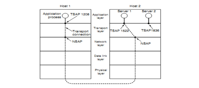
TSAP (Transport Service Access Point) to mean a specific endpoint in the transport layer. The analogous endpoints in the network layer (i.e., network layer addresses) are not surprisingly called NSAPs (Network Service Access Points). IP addresses are examples of NSAPs.
TSAP-NSAP

Application processes, both clients and servers, can attach themselves to a local TSAP to establish a connection to a remote TSAP. These connections run through NSAPs on each host. The purpose of having TSAPs is that in some networks, each computer has a single NSAP, so some way is needed to distinguish multiple transport endpoints that share that NSAP.
EIGRP has an administrative distance of 90.
 
IGRP has an administrative distance of 100.
 
OSPF has an administrative distance of 110.
 
RIP has an administrative distance of 120.
 
Hence, the EIGRP route is preferred.
The entries in the unicast IP routing table are used to make multicast forwarding decisions. You can use any dynamic interior routing system, static routes, or a combination of the two for multicast; it doesn't matter how the unicast IP routing table was formed.
46 .
What Is The Difference Between Default Route Types In Is-is And OSPF Areas?
All routes are advertised into all OSPF areas by default. This comprises OSPF inter-area routes and also external routes inserted into OSPF. IS-IS injects a default route into an area instead of advertising inter-area or external routes.
On a Cisco router, enabling IGRP is similar to enabling RIP, except that you select IGRP as the protocol and add an autonomous system number.
 
For example :

RouterA(config)#router igrp 10 (10 is the AS number)
 
RouterA(config-router)#network 192.168.0.0
 
RouterA(config-router)#network 192.168.1.0
 
RouterA(config-router)#network 192.168.2.0
Traditional routing is destination-based, meaning packets are routed based on destination IPaddress. However, it is difficult to change the routing of specific traffic in a destination-based routing system. With Policy Based Routing (PBR), you can define routing based on criteria other than destination network—PBR lets you route traffic based on source address, source port, destination address, destination port, protocol, or a combination of these.
 
Policy Based Routing :
* Lets you provide Quality of Service (QoS) to differentiated traffic.
* Lets you distribute interactive and batch traffic across low-bandwidth, low-cost permanent paths and high-bandwidth, high-cost switched paths.
* Allows Internet service providers and other organizations to route traffic originating from various sets of users through well-defined Internet connections.
 
Policy Based Routing can implement QoS by classifying and marking traffic at the network edge, and then usingPBR throughout the network to route marked traffic along a specific path. This permitsrouting of packets originating from different sources to different networks, even when the destinations are the same, and it can be useful when interconnecting several private networks.
Consider a company that has two links between locations: one a high-bandwidth, low-delay expensive link, and the other a low-bandwidth, higher-delay, less-expensive link. While using traditional routing protocols, the higher-bandwidth link would get most, if not all, of the traffic sent across it based on the metric savings obtained by the bandwidth and/or delay (using EIGRP or OSPF) characteristics of the link. PBR allows you to route higher priority traffic over the high-bandwidth/low-delay link, while sending all other traffic over the low-bandwidth/high-delay link.
In this topology, traffic from HR network & Mgmt network can be configured to go through ISP1 and traffic from Eng network can be configured to go through ISP2. Thus, policy based routing enables the network administrators to provide equal-access and source-sensitive routing, as shown here.
 Equal-Access and Source-Sensitive Routing
* Intra-Area (O)
* Inter-Area (O IA)
* External Type 1 (E1)
* NSSA Type 1 (N1)
* External Type 2 (E2)
* NSSA Type 2 (N2)
If physical interfaces are only used, the OSPF router ID is the highest IP address assigned to an active physical interface. If loopback interfaces are used, the OSPF router ID is the highest IP address assigned to a loopback interface. If the router-id command is used with the OSPF configuration, the address used with this command will be the router ID.
53 .
What is the difference between an E1 and E2 OSPF route?
An E1 route contains the OSPF cost to reach the ASBR plus the cost from the ASBR to the external route. An E2 route contains only the cost from the ASBR to the external route.
54 .
What types of routes are allowed into an NSSA?
OSPF intra-area and interarea routes, and possibly a default route. External routes from ABRs are blocked, and external routes from ASBRs are converted to N1 or  N2 routes.
55 .
What types of routes are allowed into a total NSSA?
OSPF intra-area routes and a default route. External routes from ABRs are blocked, and external routes from ASBRs are converted to N1 or N2 routes.
56 .
Assume a router has a loopback address of 135.77.9.254. Convert the loopback address to an IS-IS system ID.
The loopback address written in dotted decimal and using three digits for each byte has a value of 135.077.009.254. The system ID is 13.50.77.00.92.54.
57 .
Describe the difference between an OSPF and IS-IS backbone.
OSPF has a backbone area or area 0. All nonzero areas must be connected to the backbone through a router or a virtual link. IS-IS has a backbone area made up of a contiguous chain of Level 2 capable routers.
58 .
In IS-IS, what is the function of a Level 1-2 router?
A Level 1-2 router has two IS-IS databases.
 
* The Level 1 database is used for routing to destinations within the router’s configured area.
* The Level 2 database is used to route between destinations in different areas.
A site-to-site virtual private network (VPN) refers to a connection set up between multiple networks. This could be a corporate network where multiple offices work in conjunction with each other or a branch office network with a central office and multiple branch locations. 
 
Site-to-site VPNs are useful for companies that prioritize private, protected traffic and are particularly helpful for organizations with more than one office spread out over large geographical locations. These businesses often have to access resources housed on a primary network, which could include servers that facilitate email or store data. In some instances, a server may be the operational hub of an application essential to the company’s business. A site-to-site VPN can, in that case, give all sites full access to the application—as if it were housed within their physical facility.
 
The history of site-to-site VPNs intersects, in many ways, with the history of the internet itself. Site-to-site VPNs were a forbearer of what we now know as the internet. They were first made possible through the use of the original packet switching network named Advanced Research Projects Agency Network (ARPANET), as well as the initial uses of Transmission Control Protocol/Internet Protocol (TCP/IP). 
An internet-based site-to-site VPN uses the existing network of an organization in combination with the public internet. To set up an internet-based site-to-site VPN, you need a VPN gateway that secures the data traveling back and forth.
 
To create an internet-based site-to-site VPN, you make a tunnel that connects two networks, for which you need three components:
 
* A base network in one location
* A satellite network in another location
* A tunnel with security gateways on each end

The tunnel “burrows through” or sits on top of a physical internet connection. However, the tunnel protects the traffic flowing through it from being accessed by people using the physical network. To set it up, you need to set up a gateway at each site. The first gateway the data meets as it enters the tunnel will encrypt the data. The encryption keeps each data packet safe from users, devices, and malware that could seek to corrupt, steal, or compromise it in some way. 
 
As the data arrives at its destination, it meets the other gateway. This decrypts the data so the network on the other side can read it. Entities in the physical internet the data has to travel through while encrypted will not be able to read it. The data will remain unreadable without a second gateway to decrypt it for the receiving network.
 
The gateway may incorporate a network access server and a secure access service edge (SASE), which requires the user to enter credentials before they gain access to the VPN.
 
You can also use a firewall, which furnishes a powerful barrier that sits between the organization’s private network and the surrounding internet. The firewalls can restrict the kind of traffic allowed to go through them.
There are several factors to consider when figuring out whether to implement site-to-site VPN services. In some cases, typical IPsec is sufficient for communication between two or more locations. However, there are a few considerations that may drive a company to use VPN connections instead:
 
* The number of locations
* Business size
* The distance between each location
* The resources the locations have to share with each other

In most cases, a site-to-site VPN is a good solution if your business consists of several locations, each with employees that need to share resources provided by the main office. If you use a site-to-site VPN in this kind of situation, you can ensure that all employees have secure access to the same resources.
 
For example, suppose you have a company based in New York, but it has several branch offices, one in Shanghai, one in France, and another in Switzerland. Each location has between 15 and 20 employees. The company’s email system is housed on a central server. You also have a data server that holds important marketing collateral and proprietary information. 
 
If you use a site-to-site VPN, not only can every employee access the same resources but the data is also encrypted, keeping it safe from attackers who may want to exploit it.
Watertight Security : The VPN your company chooses must be protected by stringent security measures. The data that travels back and forth must be secure, both as it moves from point to point and while at rest in each location. This involves adequate authorization, authentication, and administration. It is also important for all practices to support the security policies of the organization, including any established best practices that have been developed by the various IT staff in each location.
 
A VPN with properly programmed gateways will only let data through if it has the appropriate authentication. Otherwise, it is discarded, which, in many cases, keeps the network safe.
 
Ease of Operations : If a VPN is difficult to use, it can cause more frustration than convenience. Users should have the freedom to access the VPN using a web browser. While it is important to ensure ease of access, this should not result in lax security practices. If users have to take an extra step to get into the VPN, the extra security may be worth the additional few moments it takes to gain entry.
 
This does not mean access has to be cumbersome. In the majority of cases, employees should be able to get into the VPN using mobile devices like laptops, tablets, or smartphones.
 
With a VPN, you can also make network administration easier. You can manage remote locations from a central office and exercise complete control over the entire network. This gives you the flexibility to upgrade your security measures, including installing new features or updating existing software—all from one location.
 
Simple and Secure Scalability : It is easy to scale a VPN. You can add a new site, user, office, or partner organization in minutes. If you do not have to put additional VPN clients at each new location, it is quick and inexpensive to incorporate additional connections. Also, in case you need to relocate a satellite office, it is easy to set up another location.
 
Business Continuity : In the event of a disaster, whether naturally caused or due to an infrastructural issue, it is important to minimize business interruption and get back up and running as soon as possible. A site-to-site VPN lets you leverage remote access immediately after an emergency has been identified. 
 
If, for example, an office is affected by a disaster, employees do not have to stop all production until things are back up and running. They can each be granted access to the site-to-site VPN, connect to the resources at headquarters, and work from home. With a VPN, you can minimize downtime and reduce the financial effects of a disaster.
 
Flexible Deployment : With a VPN, you have the power to deploy a new solution across a broad network of devices at various physical locations. You can choose which sites to provide the new solution to first, second, and so forth. This could give you the flexibility to offer training or support in controllable phases instead of tackling it all at once and potentially overwhelming your IT team.
A remote access virtual private network (VPN) enables users who are working remotely to securely access and use applications and data that reside in the corporate data center and headquarters, encrypting all traffic the users send and receive.
 
The remote access VPN does this by creating a tunnel between an organization’s network and a remote user that is “virtually private,” even though the user may be in a public location. This is because the traffic is encrypted, which makes it unintelligible to any eavesdropper. Remote users can securely access and use their organization’s network in much the same way as they would if they were physically in the office. With remote access VPN, data can be transmitted without an organization having to worry about the communication being intercepted or tampered with.
64 .
What is the purpose of the WEIGHT attribute?
If a router has more than one route to the same IP prefix, the best path is the one with the highest WEIGHT value.
65 .
What is the scope of the WEIGHT attribute?
WEIGHT has only local significance and is not advertised to BGP peers.
66 .
What is the purpose of the LOCAL_PREF attribute?
If a router has more than one route to the same IP prefix, the best path is the one with the highest LOCAL_PREF (assuming the WEIGHT attribute for the routes is equal).
67 .
What is the scope of the LOCAL_PREF attribute?
The LOCAL_PREF attribute is advertised throughout the autonomous system.
BGP uses the AS_PATH attribute for loop detection. If a router sees its own AS number in a BGP advertisement, the advertisement is dropped. IBGP routers have the same AS number so the AS number cannot be used for loop detection. IBGP neighbors will not advertise prefixes learned from one IBGP neighbor to another IBGP neighbor; therefore, a full mesh is required.
The switchport security feature offers the ability to configure a switchport so that traffic can be limited to only a specific configured MAC address or list of MAC addresses.
 
Secure MAC Address Types

To begin with, there are three different types of secure MAC address:
 
Static secure MAC addresses : This type of secure MAC address is statically configured on a switchport and is stored in an address table and in the running configuration.

Dynamic secure MAC addresses : This type of secure MAC address is learned dynamically from the traffic that is sent through the switchport. These types of addresses are kept only in an address table and not in the running configuration.

Sticky secure MAC addresses : This type of secure MAC address can be manually configured or dynamically learned. These types of addresses are kept in an address table and in the running configuration.
As with any feature configuration there are a number of different guidelines and requirements that need to be known before a configuration is implemented:
 
* Switchport security can only be configured on statically configured access or trunk ports (access or trunk); dynamic switchport modes are not supported.

* Switchport security is not supported on Switch Port Analyzer (SPAN) destination ports.

* Switchport security is not supported along with Etherchannel (Fast or Gigabit).

* When configuring switchport security on a switchport that is configured with a voice VLAN, ensure that the maximum number of MAC addresses is raised to account for the voice and data devices connected.

* Switchport security aging is not supported along with the Sticky secure MAC address type.
 
The configuration of switchport security is not overly complex; the following commands are used when initially configuring a switchport with security :

1

router#configure terminal

Enters the device into global configuration mode

2

router(config)#interface interface-id

Enters the device into interface configuration mode

3

router(config-if)#switchport mode {access | trunk}

Statically configures the switchport into access or trunk mode

4

router(config-if)#switchport port-security

Enables switchport port security

5

router(config-if)#switchport port-security maximum value [vlan {vlan-id | {access | voice}]

Configures the maximum number of MAC addresses that are permitted by switchport security; by default this is set to 1 MAC address.

6

router(config-if)#switchport port-security violation {protect | restrict | shutdown [vlan]}

Configures the switchport security violation mode; by default this is set to shutdown.

7

router(config-if)#switchport port-security mac-address mac-address [vlan {vlan-id | {access | voice}]

Configures a static secure MAC address on a switchport

8

router(config-if)#switchport port-security mac-address sticky

Configures the use of sticky learning on a switchport

9

router(config-if)#switchport port-security aging {static | time time| type {absolute | inactivity}}

Configures the use of switchport port-security aging, the aging time and/or the aging type. The default is for switchport port-security aging to be disabled.

Sources : Cisco, and more..